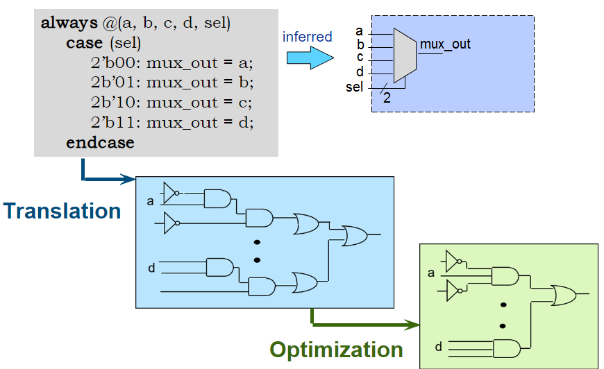
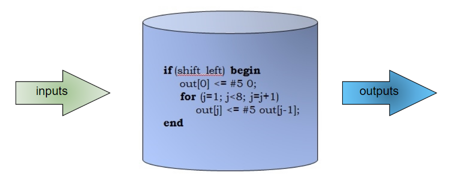
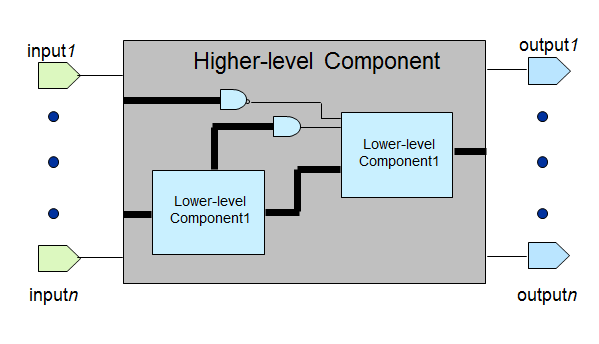
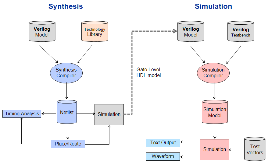
Contents Verilog HDL Overview IEEE industry standard Hardware Description Language (HDL) - used to describe a digital system. Use in both hardware simulation and synthesis. Introduced in 1984 by Gateway Design Automation. 1989 Cadence purchased Gateway and subsequently released Verilog to the public. Open Verilog International (OVI) was formed to control the language specifications. 1995 IEEE accepted OVI Verilog as Standard 2001 and 2005 IEEE revised standard. 2009 merged with SystemVerilog becoming IEEE standard 1800-2009 Terminologies HDL: A text based programming language that is used to model a piece of hardware. Behavior Modeling: A component is described by its input/output response. Structural Modeling: A component is described by interconnecting lower-level components/primitives. Register Transfer Level (RTL) : A type of behavioral modeling, for the purpose of synthesis.Hardware is implied or inferred. Synthesizable Synthesis: Translating HDL to a circuit and then optimizing the represented circuit. RTL Synthesis: Translating a RTL model of hardware into an optimized technology specific gate level implementation. RTL Synthesis Behavior Modelling Only the functionality of the circuit, no structure is mentioned. Synthesis tool creates correct logic. Structural Modelling Functionality and structure of the circuit. Call out the specific hardware. Typical RTL Synthesis & RTL Simulation Flows Typical RTL Synthesis & RTL Simulation Flows Module Structure Verilog - Basic Modeling Structure module module_name(port_list);
port_declaration;
data_type_declarations;
circuit_functionality;
timing specifications;
endmodule
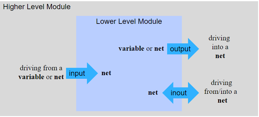
Begins with keyword module and ends with keyword endmodule All keywords are lowercase Whitespace(insensitive) is used for readability. Semicolon (;) is the statement terminator. /* … */ Multi-line comment Timing specification is only for simulation purpose Verilog HDL: Demonstration Example Verilog HDL: Demonstration Example Module Declaration Begins with keyword module Includes port list, if any Port types inout - bidirectional port <port_type> <port_name>;module full_adder(a, b, cin, sum, cout);
input a, b, cin;
output sum, cout;
...
endmodulemodule adder(a, b, cin, sum, cout);
input [3:0] a, b; // declares 4-bit input port a, b
input cin;
output [3:0] sum; // declares 4-bit output port sum
output cout;
wire c0, c1, c2;
...
endmodulePost 2001 & later module/port declaration Beginning in Verilog-2001, module and port declarations can be combined.More concise declaration section. Parameters may also be included. module adder(
input [3:0] a, b, // declares 4-bit input port a, b
input cin,
output [3:0] sum, // declares 4-bit output port sum
output cout
);
wire c0, c1, c2;
...
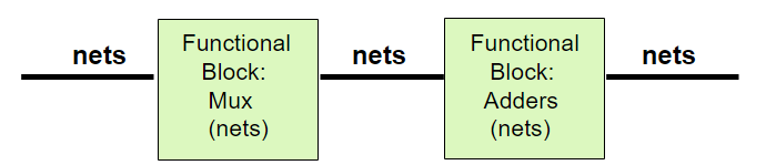
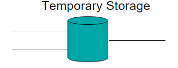
endmoduleData Types Net Data type: represents physical interconnect between structures (activity flows) Variable data type: represents element to store data temporarily.
Net Data types Type Definition wire Represents a node or a connection tri Represents a tri-state node supply0, supply1 logic 0; logic 1
<data_type> [MSB:LSB] <signal_name>;
<data_type> [LSB:MSB] <signal_name>;
Variable Data types reg : unsigned variable of any bit size.reg signed is used for signed implementation.integer : signed 32-bit variable.real, realtime, time : no synthesis support, only simulation.
Can be assigned only within a procedure, a task or a function. reg [MSB:LSB] <signal_name>;
integer count;Parameters Value assigned t a symbolic name. Must resolve to a constant at compile time. Can be overwritten at a compile time. localparam: same as parameter but cannot be overwritten.parameter size = 8;
localparam outsize = 16;
reg [size-1:0] data_a, data_b;
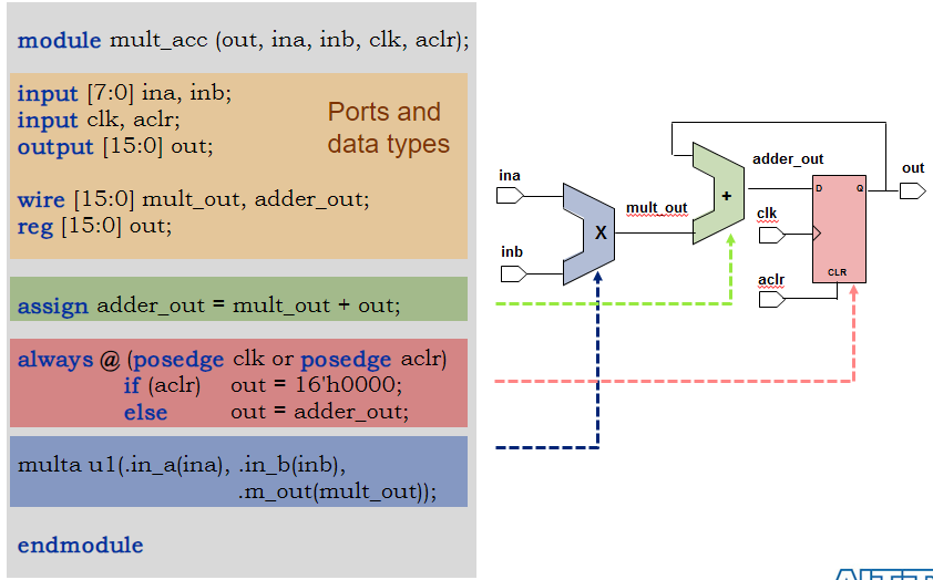
reg [outsize-1:0] out;Verilog-2001 style, include with module declaration. module multi_acc
#(parameter size = 8)
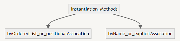
(..);Parameters can be floating parameters as well, they are defined as real parameters Instantiation Formats <component_name> #<delay> <instace_name> (port_list);<component_name>The module name of your lower level component. <instance_name>Unique name applied to individual component. (port_list)List of signals to connect the component. Connecting Module instantiation ports Two methods to define port connections module half_adder(a, b, sum, cout);
input a, b;
output sum, cout;
...
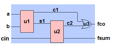
endmodulePositional Association Port connections defined by the order of the port list in the lower-level module declaration. Order of the port connections does matter Explicit Association Port connections defined by name. Recommended method Order of the port connections does not matter. .<signal_name>(<port_name>)module full_adder(a, b, cin, sum, cout);
input a, b, cin;
output adder_sum, adder_cout;
wire c1, c2, s1;
half_adder dut0(a, b, s1, c1); // Positional Association
half_adder dut1(.a(s1), .b(cin), .sum(adder_sum), .cout(c2));
// Explicit Association
or dut2(adder_cout, c1, c2);
// <basic_gate> <instance_name>(output_ports, input_ports);
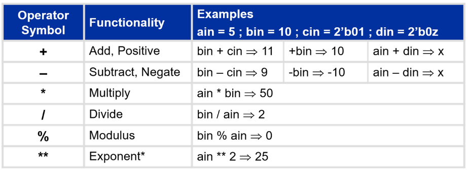
endmoduleRequirements for port connection when modules are instantiated Requirements for port connection when modules are instantiated Assigning values - Numbers Numbers are sized or unsized <size>'<base_format><number>Sized example: 3’b010: 3-bit wide binary number.The prefix (3) indicates the size of number. Unsized example: 123: 32-bit wide decimal number by default.Defaults No specified <base_format> defaults to decimal No specified <size> defaults to 32-bit wide number 1. Decimal ('d or 'D) 16'd255 - 16-bit wide decimal number
2. Hexadecimal ('h or 'H) 8'h9a - 8-bit wide hexadecimal number
3. Binary ('b or 'B) 'b1010 - 32-bit wide binary number
4. Octal ('o or 'O) 'o21 - 32-bit wide octal number
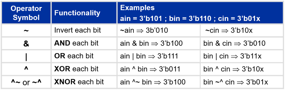
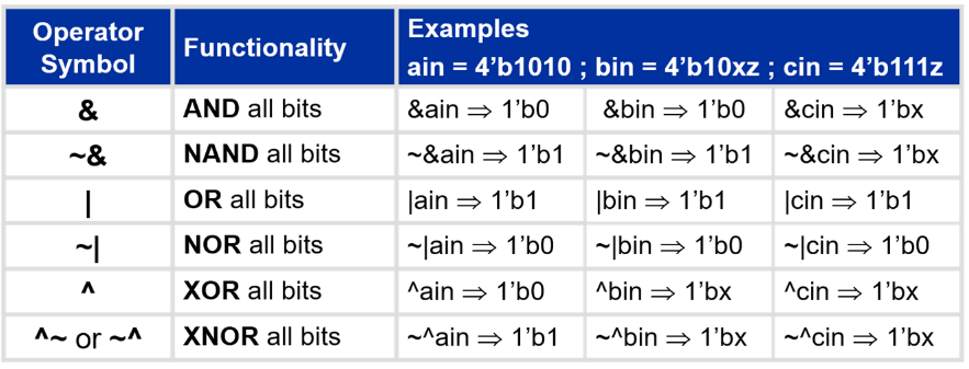
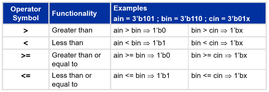
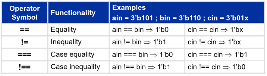
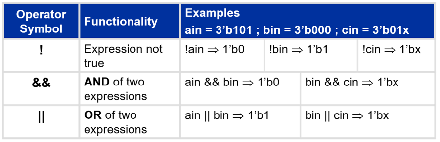
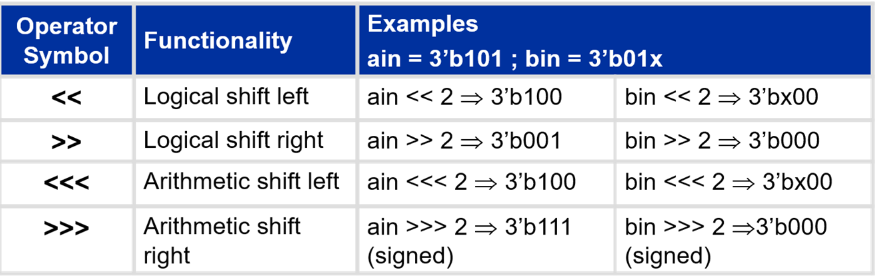
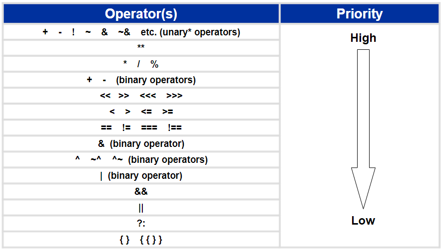
5. Signed ('s or 'S) 16'shFA - signed 16-bit hex value Numbers Negative numbers: specified by putting a minus sign before <size>Legal: -8’d3 : 8-bit negative number stored as 2’s complement of 3Special Number Characters ‘_’ (underscore): used for readabilityEx: 32’h21_65_bc_fe - 32-bit hexadecimal number ‘x’ or ‘X’ (unknown value)Ex: 12’h12x - 12-bit hexadecimal number, LSBs unknown ‘z’ or ‘Z’ (high impedance value)Ex: 1’bz - 1-bit high impedance number Operators Arithmetic Operators Treats vectors as a whole value. Results unknown if any operand is z or x Carry bit(s) handled automatically if result wider than operands Carry bit lost if operands and results are same size Bitwise Operators Operates on each bit or bit pairing of the operand(s) Result is the size of the largest operand X or Z are both considered unknown in operands, but result maybe a known value Operands are left-extended if sizes are different Reduction Operators Reduces a vector to a single bit value X or Z are both considered unknown in operands, but result maybe a known value Relational Operators Returns a 1-bit scalar value of Boolean true(1) or false(0) X or Z are both considered unknown in operands and result is always unknown Equality Operators Returns a 1-bit scalar value of Boolean true(1) or false(0) For equality/inequality, X or Z are both considered unknown in operands and result is always unknown For case equality/case inequality, X or Z are both considered distinct values and operands must match completely Logical Operators Used to evaluate single expression or compare multiple expressionsEach operand is considered a single expression Expressions with a zero value are viewed as false Expressions with a non-zero value are viewed as true Returns a 1-bit scalar value of Boolean true(1) or false(0) X or Z are both considered unknown in operands and result is always unknown Shift Operators Shifts a vector left or right some defined number of bits Left shifts (logical or arithmetic): vacated positions always filled with zero Right shiftsLogical: Vacated positions are always filled with zero Arithmetic (unsigned): Vacated positions filled with zero Arithmetic (signed): Vacated positions filled with sign bit value (MSB value) Shifts by values of X or Z (right operand) return unknown Miscellaneous Operators Operator Precedence () used to override default and provide clarity Unary operators have only one operand